Friday, October 26, 2012

I haven't posted in a while

 After the big rush to get ready to launch in September, I've taken time off from working on the boat.  I have a punch list of 30 or so items left before I consider the boat done.  This includes things like the electrical system, making the hatch waterproof (the boat doesn't leak from the bottom, but it does leak from the top), fairing and painting the rudder cassette, creating the motor mount, installing hiking straps, etc., etc.  Fortunately, a good percentage of these projects can be finished in the basement over the winter.

I'm posting a couple of pictures here, just for fun.  The one on the right shows the standing rigging on the boat.  As described before, I used t-ball hooks and backing plates to anchor the shrouds to the mast.  I installed stainless steel lined plastic fairleads in the spreaders for the shrouds to go through.  As you can see on the upper spreader there is only one set of fairleads whereas there are two on the lowers.  The two fairleads on the lowers are in-line and match the angle of the chain-plates.

The picture to the right is just eye candy.  A line of thunderstorms went by just before sunset,with blue sky behind them.  The colors and intensity of the reflections were amazing.  As far as the boat is concerned, the photo does show the hatch cover which matches the cedar strip cabin.

Saturday, September 15, 2012

Splash


 I had dozens of small tasks that I needed to accomplish before we took the boat on vacation.  I finished most of them, but then I settled for leaving a few un-done.  In any case, when I get back, I'll post details on some of those steps.  For now, here are some pictures from this week in Maine.


 My son Matt - last seen in this blog after we flipped the boat over last Thanksgiving.

Friday, August 24, 2012

Rudder attachment

I fabricated the rudder cassette this week.  For those who are not familiar, the cassette allows the use of a simple rudder foil which is inserted into from the top.  This allows the sailor to raise the rudder in shallower water and still have some steering.  It also makes it easy to remove the rudder foil when pulling the boat onto a trailer.

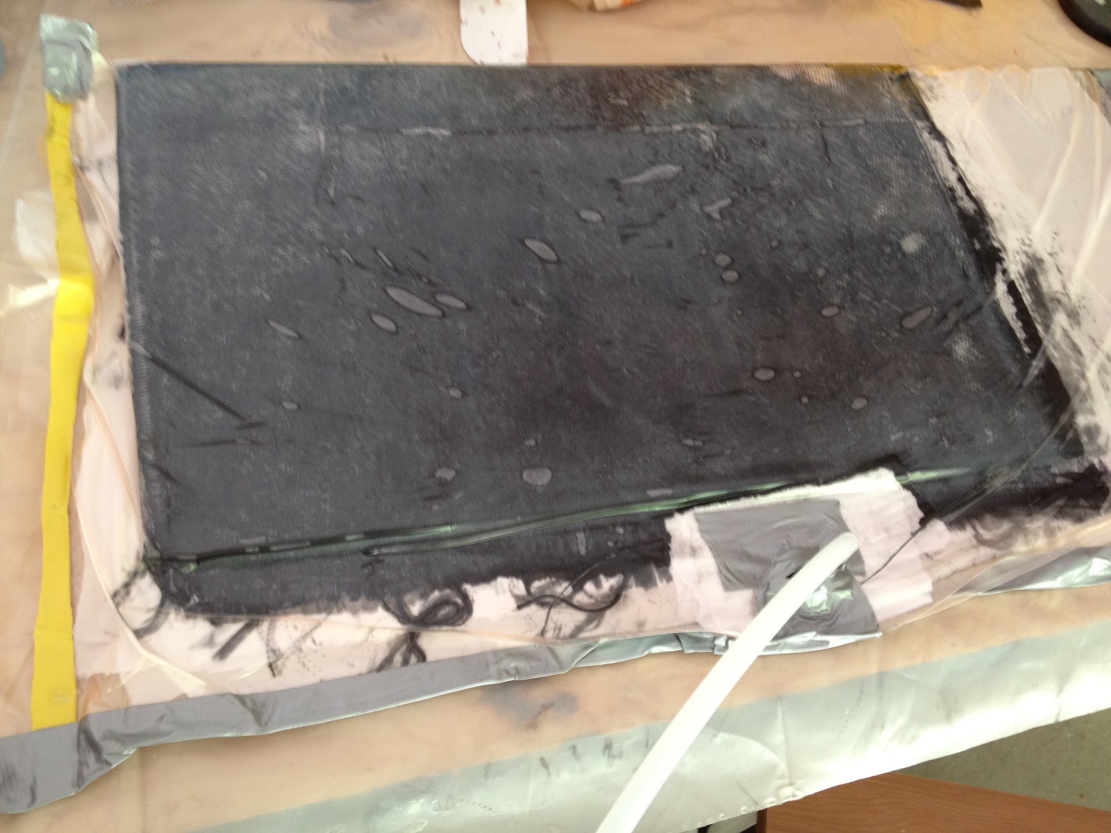
I fabricated the cassette using the rudder foil as a mold.  The first step was to wrap the finished rudder in 6 mill plastic with a couple of wraps to provide decent clearance between the cassette and the foil.  I then used the same CF sleeving that I used to create the rudder foil for the inside and outside layers of the cassette, with layers of uni-directional carbon fiber in the middle layers.  Once the epoxy set, I then glued on some "stand-offs" to hold some G10 (fiberglass) tubing in front of the leading edge of the rudder cassette.  The tubing has a 3/8" inside diameter and is intended to hold the stainless steel pin.  Once the epoxy was dry, I faired the area around the tube to insure a nice smooth finish and then wrapped 4" wide unidirectional strips of CF around the G10 tube.  One point is that I used a single length of tubing along the leading edge of the cassette so that I didn't have to worry about aligning different sections of tube.  I later cut off the tube sections that I didn't want.  The picture above shows the cassette before I trimmed it to length.  It also shows the "handle" which will attache to the tiller.  The handle was fabricated using a piece of ordinary pink insulating foam from Home Depot.  I turned the foam on a lathe to get the shape that I wanted (a slight taper from back to front).  I then wrapped the foam with release cloth, then layers of CF (sleeves and uni) and then wrapped that in release cloth.  Once everything hardened, I removed most of the foam using a 1" hole spade (flat drill bit).  Using some needle-nosed pliers I took out the inside layer of release cloth, by just grabbing a corner of the cloth and twisting.  After taking off the outside layer of release cloth and then cutting a U-shaped channel in the handle, I then epoxied it onto the cassette.  I did drill a hole from the top of the handle to allow the rudder pin to be inserted from the top.

 The picture to the right shows the cassette mounted to the stern of the boat with the handle attached to four heavy duty gudgeons (the stainless steel straps which hold the rudder pins) from Racelite hardware.
There have been some broken rudders on some of the earlier i550 boats.  Some of these failures were due to the rudder attachment points bending.  With the four gudgeons and a single 3/8" stainless steel pin, I'm confident that these won't be a point of failure (hopefully the cassette or the rudder foil itself are up to the task)

Friday, August 17, 2012

The mast is vertical - or it was earlier today

 I hoisted the mast for the first time today.  The goal today and the big task was to cut the shrouds to the proper length and then connect the sta-lok terminals that I'm using to connect the stays to the boat.  I used 3/8" line as temporary shrouds and head stay to hoist the mast.  I then measured and cut to length the real head stay and each of the shrouds, and then connected them to the Sta-Master calibrated turnbuckles that I'm using.

One of the best tips that I received at one time or another on one of the forums was to use a Dremel tool with a cut-off wheel to cut the shrouds.  This was so much easier than trying to cut these things with a hack-saw.

Like every other task on the boat, I got pretty good at measuring, cutting, and attaching the sta-lok terminals just as I wrapped up the last one.

Here are the Sta-loks connected to the Sta-Masters.  I used Sta-Master turnbuckles because I've had good luck with them for (many years) on our e-scow.

Monday, August 13, 2012

Foils finally finished

Both the rudder foil and the keel are now finished after applying three coats of primer, a bunch a fairing material and four coats of Interlux Perfection paint.

I couldn't be happier with the way these came out.  The only things left to do are:

  • Fasten a stainless steel plate on the top of the keel.  This will be done with the "Ikea" technique of drilling holes horizontally through the keel which will hold a nut and washer and then drilling down from the top for the bolt which holds on the top plate.
  • I'm going to fabricate a handle for the top of the rudder out of cedar and mahogany.  I left a 1-1/2" carbon fiber tab on top of the rudder to hold the handle.
  • I still need to mold the rudder cassette.  Now that the rudder is finished, I can use it as the mold for the cassette. 

Sunday, August 5, 2012

A ton of small projects need to be completed to finish this boat

 In the past few couple of weeks I've been working on several different projects tying to get the boat done.  The three main categories of work have been on 1) the keel and rudder foil, 2) Standing rigging, and 3) deck hardware.  Items 2 and 3 are a bit of a hold-up because I'm still waiting for delivery of many of the parts that I've ordered.   Here are a few of the activities:


I attached the gooseneck fitting to the mast using pop rivets.
The spreader collars were glued onto the mast using West System G-Flex epoxy.  I used the West system Aluminum prep kit prior to gluing the collars.  The spreaders aren't shown in these pictures, but I trimmed the length of the upper spreaders from 36" to 30".  They just didn't look right.

I riveted on backing plates onto the mast for six shrouds.  I'm waiting for the backing plate for the head-stay to come in.


And finally, I've put a lot of work into fairing, priming and sanding the the rudder foil.  The picture below shows the keel with it's first coat of Interlux Perfection paint.

Tuesday, July 24, 2012

Sails

I picked up the sails for the i550 from Farrar Sails in New London CT this weekend.  The main and jib are Kevlar/Mylar tri-radials.  The picture to the left shows the spinnaker.  At almost 500 sq. ft. I don't think that we will lack for downwind sail area.  Of course it will look a whole lot better filled out on a reach than it does on the grass.

I have most of my standing rigging on order so I'm hoping to be able to hoist the sails soon.

Thursday, July 12, 2012

Monday, July 9, 2012

Rudder foil

 In the last few days, I vacuum bagged the rudder foil.  I built this in a very similar fashion to the spreaders I made a while ago.


I started with foam inserts from Flying Foam.  I ordered a tapered insert for the bottom 2/3's of the foil and a straight section for the top part that will contact the rudder cassette.  The maximum chord (front to back distance) is 10", but I trimmed a bit off of the trailing edge since it would just get distorted during the fabrication since the edge was so fine.  


I split the foam inserts length-wise and then glued them back together around a piece of 1/4" Hydrotech which acts as a spar of sorts.  The plywood is really just intended to keep the outer skins of the foil from separating from the foam inserts.  


The foil started with an interior layer of CF sleeve.  I used an 8" sleeve which easily conformed to the foil (which varies from 10" at top to 6" at the bottom).  I then added three layers of unidirectional CF which taper from the top to the bottom so that at the bottom only a small section of one layer of uni is used, and then covered the whole thing up with an outside layer of the CF sleeve. 


The photo above shows all of that being vacuum bagged.  And the photo to the left shows the result afger I trimmed the ends.


A little bit of fairing, and then I'll use the foil as the mold for the rudder cassette.


There have been a bunch of broken rudders on i550's.  Hopefully, this one is strong enough to hold up.


A bit of an add-on to the original post:


The foam that I used was not stiff enough to insure that the process of vacuum bagging wouldn't distort the foil, so the first layer of CF sleeve was not bagged.  Instead, I used the same technique that I used to create the spreaders, using the female foam sections that came from Flying Foam to provide pressure on the wetted-out CF sleeve.  The picture to the right shows the result.  You can just barely see the plywood "spar" at the bottom of the picture.  I also shaped the foam to round the leading edge using a surform tool.  Once the initial sleeve hardened, the foil was plenty stiff enough to vacuum bag.  Of course for all layers I used release cloth and absorber cloth.

Tuesday, July 3, 2012

Cabin top all shiny looking

After a lot of sanding and coating with epoxy and more sanding, I finished the cabin top and the cockpit curves with Interlux Perfection clear.  


The photo to the left shows the cabin top as well as the oyster white colored non-skid surface on the deck.  I'm debating whether or not to put clear non-skid on the cabin.

Thursday, June 28, 2012

Base coat is done on deck

 I'm done with the base coat on the deck of the boat.  I put on three coats of Interlux Perfection Snow White.  


The pictures to the left show the boat after I removed the masking tape which was protecting the cabin top and the curved corners in the cockpit.  As I'm mentioned several times earlier these were built using cedar strips, and my intention is to leave them natural.
The next step is to mask off the areas on the deck where I will not have a grip surface and then paint those areas.  Hopefully the non-skid will be done in a couple of days.  


The final step (as far as painting is concerned) will be to finish the cedar strip portions with Perfection clear.  

Sunday, June 24, 2012

Deck painting

More sanding, fairing, and painting.  The first step was to mask off the finished hull with masking tape and rosin paper so that the new paint doesn't mess up the nice paint on the bottom.  With the green tape and the pink paper, the boat has a distinct easter egg look.   
 The boat is just about ready for its final (third) coat of primer.  One more light sanding and of course clean up is needed before putting down the paint.  


We've decided to go with Interlux Perfection snow white for the parts of the deck that don't have non-skid on them (the same as the bottom).  For the non-skid I bought Awlgrip course non-skid beads and we're going with Perfection oyster white for the non-skid areas


Some time last summer, I described building the cabin top using the cedar strips with some mahogany for accents.  I fabricated a mast step platform today out of a piece of solid mahogany.  This block of wood had to be shaped so that its bottom matched the contour of the cabin top, and so that the top would be level.  I did this by transferring the cabin top curve onto the block with a pencil, and then used my table saw to cut grooves that matched the curve.  Using a belt sander, I cleaned up the grooves and shaped the curve in the lateral direction (side to side). The picture to the right shows the mast step platform glued to the cabin top above frame 89.


The block was also sized to support a stainless steel deck organizer that I bought from Dwyer Mast.

Sunday, June 17, 2012

Boat is upright again


 We rolled the boat back over today and put it on the trailer.  Rolling it over was actually very easy.  We just put some plastic sheet on the grass and tipped the boat and cradle over and rolled the boat right off onto the plastic.  Picking the boat up to get it on the trailer was a bit harder because the paint is actually pretty slippery and it's hard to get a good grip on the boat.  However with my two younger sons and my wife helping, we made pretty short work of getting the boat onto the trailer.  The only thing left to do once the boat was on the trailer bunks was to adjust the winch stanchion so that it just touched the bow.  We actually only had to move it an inch or so from how it came from the factory.

The pictures to the right show the boat on the trailer.  The top photo shows my two helpers.


More about the trailer


The picture to the left shows the completed  trailer waiting for the boat.  This particular trailer, a Ventura 1300, seems to be very well suited for an I550 because the back cross-brace lines up very nicely with frame 169 and there is another cross-brace right under where the keel will be let down.  I still need to attach a keel bulb platform to this cross-brace, but that will happen after I lift the boat in order to install the keel foil.

Friday, June 15, 2012

Hull painting is done

I put the final coat of paint on the bottom of the boat.  Of course when you see the bottom all glossy you see every imperfection.    However, at some point you have to say; "good enough."  I have a small bit of work to do inside the boat while its upside down, but I'm planning on flipping it back over in a couple of days.  By then, the trailer should be ready to take the boat.  


Next up, the deck still needs to be faired, sanded, and painted.  I did a preliminary fairing before we flipped the boat over, but there is a lot of work to be done in the next couple of weeks.

Saturday, June 9, 2012

Trailor


In between coats of paint I molded bunks for the trailer at frames 89 and 169.  To do this i laminated 4" wide strips of 1/4 hydrotek plywood on the bottom of the boat at those frame locations.


I bought trailer a while ago for the project.  I took off the powerboat bunks so that I could fit the ones that I built on the boat.  The rear bunk bolts nicely onto the back frame on the trailer.  However, the front bunk needed brackets to hold it in place.  So anyway, I dusted off my welding skills and and created my own brackets.  For the metal I took the supports for the old powerboat bunk and cut them in half and then welded them in place.  I'll write more on this whole procedure when I have time in the future.


Monday, May 28, 2012

Who needs a workout program?

 When you have a boat to sand, fair, sand, paint, sand, fair, sand, paint, . . .
 Second coat - with a touch of graphite powder added to tint the paint gray.  I took the boat outside so that I could see the imperfections.  I also took the opportunity to clean out the garage under the boat.
 Second coat after sanding and fairing - I finally filled in just about all of the pin-holes and glass weave
Third coat - after sanding the bottom again of course.

Saturday, May 19, 2012

First coat of primer

I applied the first coat of primer today to the hull using using Interlux Primekote epoxy paint.  The photo to the left shows the boat bottom with the primer.  I spent most of the time trying to make sure that all of the glass weave and the "pin holes" were filled in and didn't worry too much about complete coverage.  I did this by rolling on the paint with a foam roaler and then by going over the wet paint with a bondo spreader to make sure that the holes were filled.  Tomorrow  I'll sand the bottom and start filling in the low spots with fairing compound.  Overall the hull looks very good and I don't think that I'll need to do too much fairing


The picture on the right shows the keel after priming.  The keel surface actually was pretty smooth so the primer covered pretty well.

Monday, May 14, 2012

Keel

 All of my work on the boat this weekend revolved around the keel.  I first widened the slot in the bottom of the hull (which I cut some time ago), using the keel sleeve as a template and a saber saw for the cutting.  I then laid some carbon fiber cloth into the sides of the slot, and onto the surface of the hull.  Next, I inserted the keel sleeve into the keel box using thickened epoxy to glue the sleeve to the bottom of the hull.  At that point, the keel sleeve protruded from the bottom of the hull a bit, but was level with the top of the keel box.  Once the epoxy dried, I then cut off the excess keel sleeve using a multi-tool with a flush cut-off blade on it.  I've found this tool to be invaluable in this project.


Next, I applied two layers of fiberglass cloth over the bottom of the keel sleeve.  I used masking tape and plastic to cover the inside of the sleeve so that no unwanted epoxy got into the sleeve.  


The photos to the right show the results.  The top photo shows the bottom of the hull.   I haven't cut the fiberglass over the slot yet, but will do that soon.  I've put a first layer of fairing compound over the edges of the glass cloth.  The other photo on the right shows the top of the keel sleeve inside the keel box.  I'm planning on filling the gap between the two with expanded polyurethane foam.  


I also joined the keel foil to the keel bulb this weekend.  Rather than using bolts to connect the foil to the bulb, I bought threaded stainless steel rod as well as stainless washers and nuts.  I used rod since the length that I needed varied from front to back.  I could have bought bolts of a given length and then changed the depth of the countersink to fit but I thought that the threaded rod would be easier.  The picture to the left shows the holes drilled through the bulb and the countersunk holes to make room for the washers and bolts.  I'm not sure where I read this, but someone suggested using milk as a lubricant for drilling the holes in the lead instead of cutting oil.  That actually worked very well.  Using milk avoids having to clean the oil off of bulb with degreaser prior to coating the bulb.  


The final photo shows the assembled foil (before cleaning up the epoxy mess).  When putting these two parts together, I first poured in a few ounces of epoxy / colloidal silica mix (West 406).  I then pushed the foil down into the slot in the bulb (which of course caused the epoxy mixture to rise up), and then put the rods through the holes and attached the washers and bolts.  I then made a thinner mixture of epoxy and 406 and filled the slot to the top.  Finally, I made some fairing compound (a mixture of epoxy and West 407) to cover the washers and nuts.


As it turned out, at 175 lbs. my keel is slightly under weight (the class limit is 185 lbs.).  I made the slot in the bulb larger than it needed to be because I didn't want to have to trim the foil to fit.  I think that with a bit tighter tolerance there, I would have been right on the 185 lb. weight.  


If you notice, just about all of the photos of the keel bulb on this site show the bulb sitting on a pile of sand.  The sand makes it very easy to put the bulb in almost an orientation while I scrape, fair, and sand it.  My wife is looking forward to my cleaning up the mess soon now that I'm almost ready to prime and paint the keel.


A final note on mixing thickeners, whether for bonding, making filets, or fairing:  I find it much easier and a whole lot less mess to do all of my mixing in zip-lock bags rather than using cups and a mixing stick.  Some of the thickening materials are very fluffy and light weight and float in the air pretty easily.  Virtually all of them are very bad to breath in.  I just measure out an appropriate amount of thickener into the zip-lock bag (you have to use the heavier freezer bags), and then pour in the right amount of mixed epoxy resin and hardener.  I then mix the filler with the epoxy mix by just squishing the bag around for a while.  When it's mixed, I let out the excess air and then cut off a bottom corner of the bag.  I then apply the mixture just like you would frosting when decorating a cake.  The "recipes" for the mixtures vary by type of filler, but in general, a cup and a half of filler with an 8 shot mix of epoxy/hardener is a pretty good starting point for a mixture with a mayonnaise consistency.


Monday, May 7, 2012

Keel Sleeve

I created the keelbox structure out of wood and carbon fiber quite a while ago (described below).  However, I always intended to put a foil shaped liner inside of the rectangular keelbox.  The liner extends the full height of the keel-box structure will be attached to the hull at the bottom and will be water-tight.


Take 1

I had some luck in the past with hand molding Carbon Fiber cloth around items and then just wrapping it with release cloth.  So in my first attempt, I wrapped several layers of plastic around the keel foil and then applied a four layers of 11 oz CF cloth over the plastic.  I then covered that with release cloth and clamped the bottom of the cloth with spring clamps.  Unfortunately, the sleeve that resulted was really lumpy both on the inside and the outside.  Even though no one is ever going to see this thing once it's installed, I just couldn't use something so ugly on the boat.  


Take 2
So I started over on the sleeve with a few changes.  1) I used alternating layers of glass cloth and CF instead of straight CF, 2) I mixed epoxy with graphite powder for the inside layers, and 3) I vacuum bagged the whole thing.


The graphite powder is supposed to make the inside of the sleeve much more slippery and to make retracting the keel much easier over the life of the boat.  I've also learned a thing or two about vacuum bagging while doing this boat project.  Using release cloth between the "bag" and the item yields a much nicer surface.  The second picture here, shows the sleeve while the vacuum was being applied.  I put the absorber cloth underneath the whole sleeve and wrapped the entire thing with the peel-ply.


The final picture shows the result.  The sleeve came out beautifully.  The next step is to open up the trailing edge the sleeve and then re-seal it with CF tape.  This is to give a bit more room inside the sleeve so that the foil doesn't bind.  

Sunday, April 22, 2012

Casting the Keel bulb

 Over the last week or so, I cast the bulb for the keel.  As I mentioned in a previous post, Chad (http://i550knotracing.blogspot.com/) created a "community" bulb plug that I used in creating the concrete mold for the bulb.  I decided to cast the bulb in one piece rather than in halves like some of the other builders.  


 The photo to the left shows the mold and the stainless steel pot that I used to melt the lead. The light weight ladle shown was just used for skimming scum off the top of the lead.  For the actual casting, I bought a Rowell #6 casting ladle from Amazon.  The handle of the  casting ladle is just visible on very left of the photo.  I highly recommend this ladle.  It has excellent size and strength.  My wife actually likes its appearance and wants to use it for decorations later.  I also used a Bayou Classic propane cooker (also bought through Amazon).  This cooker is designed for crawfish boils and puts out a lot more BTU's than your average turkey fryer.  


You can also (barely) see in the photo above that one end of the mold is sitting on a 4X4 and the other end is supported by a hydraulic car jack.  This turned out to be a pretty good idea because it allowed me to tilt the mold a bit so that the molten lead flowed either forward or backward to the ends.  One change that I definitely would have made to this set up is that I would have put the mold closer to the molten lead pot.  Not only would this have reduced the lead drips on the driveway, it also would have made the process faster, eliminating some of the problems that I'll describe below.

The picture to the right shows the plug after I dumped it out of the mold and after I dug out the insert for the keel foil.  A comment about the insert - I made a mold for the insert by wrapping fiberglass around the keel foil with plastic between the glass and the foil.  After the epoxy set, I then removed glass form and then shaped one end so that it fit inside the bulb mold.  Before pouring concrete into the form, I drilled holes in the bottom of the mold and inserted a section of wire coat hanger  in a U shape.  The coat hanger was for two purposes 1) to make the foil insert hold together and 2) to hold it down so that it doesn't lift off and float in the lead.  If I had it to do over again, i would have added a lot of sand to the concrete mix that I poured into the foil insert form, to make the insert almost like a sand casting mold.  It was a lot of work getting the insert out of the bulb, and I think that extra sand would have made the concrete much weaker and easier to remove.  


The final picture here shows the bulb with fairing compound on it next to the original mold plug that was made by Chad.  


Here were some of the problems that I ran into in creating the casting:  First, as mentioned above, I did not work fast enough in pouring the lead and there was noticeable layering of the lead in the casting.  Secondly, if I were to make the mold again, I would have added at least one more pouring hole that was away from the keel foil insert.  The two holes that I had were on top of the keel foil insert which substantially slowed down the pours and I ended up with some voids on the top (really the bottom) of the plug.  I later filled these voids by pouring additional lead onto the plug.  This left a very uneven surface on the bottom of the plug.  I filled in these irregularities with fairing compound.


The final change that I would make if I were to cast this bulb again is that I would have melted all of the lead at once instead of adding to the pot as I went along.  I'm not sure why I didn't do this, although I was thinking that I didn't need all of the lead that I bought (I bought about 200 pounds), and that it would be easier to not melt the unneeded lead.  This was a mistake which again slowed down the process and resulted in some of the layering in the lead.  I ended up with a 30 or 40 pound ingot at the end of the process anyway.


My next step for the bulb is to wrap the whole thing in either carbon fiber or glass cloth.  I'm pretty sure that this step isn't necessary, however with the visible layers in the bulb the last thing I want is for a chunk of the bulb to fall off some day.